
The ZBD model alternating-current transformer was invented in 1885 at the Ganz Works in the Austro-Hungarian Empire by three Hungarian engineers: Károly Zipernowsky, 0ttó Bláthy and Miksa Déri (ZBD comes from the initials of their names). Today, transformers are everywhere, feeding various voltages into our homes and businesses. When a transformer fails in a commercial or industrial environment, that failure can disrupt a significant portion of your facility operations.
When we help clients through a Criticality Assessment of their infrastructure assets, main transformers with power ratings of 500 KVA and above usually rank very high in the Risk Priority Number tables. With their high cost of replacement, long lead times of typically 12 weeks or more, high in/out swap costs and with many modes of failure impossible to repair onsite, transformers can become a weak link for reliability in your electrical distribution system. While an electrical distribution system that has been designed for redundancy, such as Main-Tie-Main configurations with each transformer loaded at less than 50% of nameplate capacity, can alleviate the impact of a failure, this is not the only consideration. Large amounts of fault energy are available making some failure modes potentially hazardous to personnel and many transformers are oil filled making flammability and environmental impacts additional considerations. It is much better to come up with ways to detect problems and prevent failures in the first place. A transformer failure can easily add up to tens of thousands of dollars in repair and downtime costs.
Fortunately, there are many types of Condition Based Maintenance (CBM) technologies that can be employed to attempt to catch the early warning signs of impending failure on transformers. Infrared inspection can detect loose connections, weak crimps and cable creepage due to thermal cycling. Contact ultrasound (structure borne ultrasound) can detect loose windings and other mechanical issues. Airborne ultrasound can detect arcing, tracking and corona all of which emit high frequency signals in the ultrasound spectrum above 20 kHz. Ultraviolet (UV) cameras can be used to confirm the exact location of a corona event. Visual inspection can detect airborne contaminants, water ingress and pest ingress. Many electricians have been “surprised” by a snake, spider or rodent who are attracted to the warm, dry innards of transformer terminal chambers.
Fortunately, there are practical solutions that exist for virtually all these inspection types that “substitute” safer methods of data collection via a safety-by-design approach and the use of Electrical Maintenance Safety Devices (EMSD).
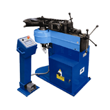
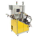
Maintenance Inspections Solutions, like those available from FLIR, can be installed on virtually any transformer and allow users to perform visual, infrared and ultraviolet inspections through a single device. Large format IRW-XPx rectangular windows mean that a single unit can be used for the LV connections and another for the HV connections on a transformer. While manipulating the cover of these types of windows, the equipment stays in a closed and guarded condition and the technician does not violate the restricted approach boundary so, per NFPA 70E Table 130.5 (C), they do not need to wear any special PPE as there is no increased likelihood of an Arc Flash occurrence.
Oil sampling ports can also be brought outside of the transformer cable compartment with several vendors offering retrofit kits that permit safe sampling as well as providing an optional external pressure gauge and nitrogen insert to relieve vacuum. Of course, contact ultrasound and PD (TEV) detection are performed on the external skin of the equipment in a closed condition and so no special Electrical Maintenance Safety Device (EMSD) is normally required for that type of inspection.
The optimum frequency of different inspection techniques is a function of the criticality of the assets in question. Following a cross functional team Failure Modes and Effects Analysis (FMEA) approach, each facility should attempt to classify their assets based on replacement cost, lead time, average repair cost, Mean Time to Repair (MTTR), potential safety impacts of failure, potential environmental impacts of failure and cost of downtime for the asset. Assets are then classified as Critical to the operation of the facility, Important to the operation of the facility or as Support assets with limited impact to the facility based on an agreed upon point system.
Table 1 provides a normal recommendation for inspection frequency for the different CBM technologies based on transformer asset criticality.
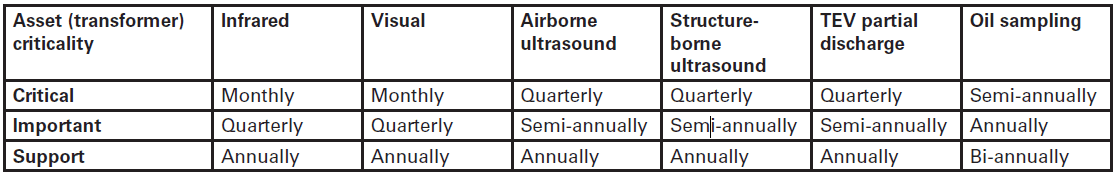
Table 1: Inspection Frequency Recommendation by Asset Criticality and Technology
It is imperative that data be collected and trended over time. For many of these measured parameters, a baseline can be set for “normal” operation shortly after the transformer goes into service.
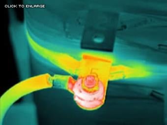
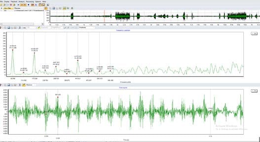
Top: Thermal image shows hot transformer tap due to loose cable connection (Image courtesv. of the lnfraspection Institute). Bottom: Ultrasound software picking up arcing fault.
Visual
• dust ingress, water ingress, pest ingress
• water stains from previously standing water
• corrosion
• visual signs of partial discharge (if detected by other CBM techniques)
• fan operation
• oil leakage
• soiled bushings
Airborne Ultrasound
• decibel values at pre-determined test points
• analysis of waveform (time and frequency domain analysis) to determine nature of PD
Structure-borne Ultrasound
• decibel values at defined test points
• waveform analysis for fault type determination
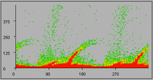
Phase-resolved partial discharge plot and surface tracking on insulator (Courtesy IPEC Ltd.)
TEV (Partial Discharge)
• decibel values at pre-determined test points
• phase-resolved partial discharge plots (comparative analysis for trends)
Oil Sampling
• oil pressure (gauge reading)
• oil temperature (gauge reading)
• oil quality (acidity, moisture content, dielectric properties)
• dissolved gas levels (ppm) including atmospheric gases, oxides of carbon, hydrocarbons and hydrogen
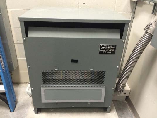
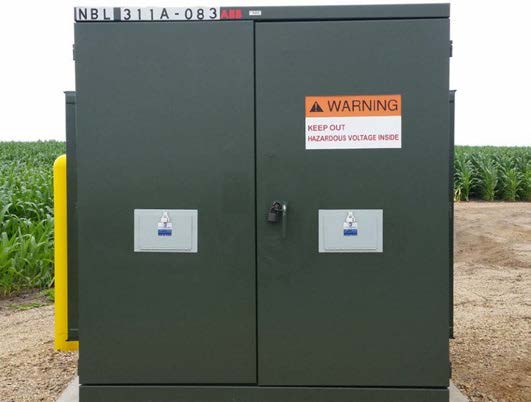
Top: Custom replacement dry transformer panel-front with a built in maintenance inspection window. Bottom: One large format maintenance inspection window is fitted on the LV side and another on the HV side of an oil-filled pad mount transformer allowing for inspection of all the internal connections.
To summarize, the use of EMSD like Maintenance Inspection Windows and external Oil Sampling ports on transformers can take the danger out of the CBM data collection tasks and eliminate the need for energized open panel work. With the risks eliminated, the inspection becomes possible with a single technician with no cumbersome arc flash PPE required - meaning the data collection can be done much more efficiently as well. With increased inspection frequency, the potential problems that lead to unexpected failures of transformers can be detected earlier and preventative intervention can be initiated. Not only does this ensure compliance with NFPA 70E guidelines, but it also makes economic sense to monitor and protect your critical transformer assets. Experience has shown that transformer protection by fuses alone is not adequate to prevent fires in the event of a short circuit. The key is to prevent the possible causes of a short circuit by detecting the early warning signs with CBM techniques.
-160x160-state_article-rel-cat.png)


-160x160-state_article-rel-cat.png)

-160x160-state_article-rel-cat.png)

-160x160-state_article-rel-cat.png)