
AIR
Low dielectric (~1), high velocity material i.e. EM waves travel almost at the speed of light. In air the emission pattern of GPR antennas is broader than in the ground. It is recommended to place the GPR as close to the ground as possible to direct emission energy further into a material. Some applications of GPR include emission exclusively in air.
GROUND / SURVEYED MATERIAL
Higher dielectric (>1), lower velocity materials than air. In ideal conditions when the surveyed material is homogenous, an operator of a GPR can expect precise calculations of achieved depths. Transmission into a lower-velocity material (such as from the air into the ground) causes the beam to get narrower. It is recommended to be aware of the composition and electrical properties of the surveyed material to be able to read radargrams accurately. Humidity in a material is a major cause for signal attenuation.
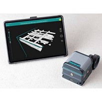
RADARGRAM
The image produced by the signal from the receiver antenna is called a radargram. It is the reflection of the emitted EM beam by the transmission antenna of the GPR colour coded by a carefully selected set of palettes. Palette design is important as it can highlight even the slightest changes in data.
TIME WINDOW
The travel time of a beam of EM waves from the GPR into a material. More specifically, it is the Rx module's preset time frame within which it listens for reflections of the EM beam sent by the Tx Module. Time windows play a crucial role in determining the depth of a detected object. It is usually marked on a radargram's Y-axis.
OBJECT FOR DETECTION
The larger the difference between an object and its surrounding material in terms of electrical properties (dielectric constant), the stronger the signal will appear on a radargram (more contrast). Sometimes a single object may produce several reflections one on top of the other caused by cavities within it - for example a pipe.
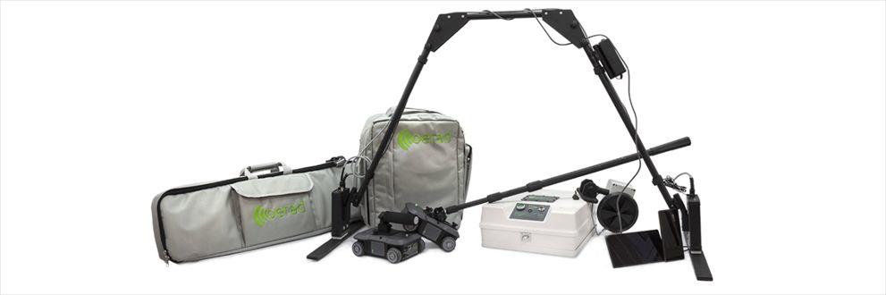
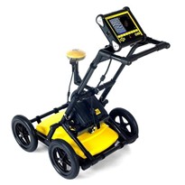
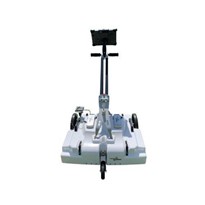
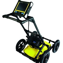
GPR
A high precision tool for imaging subsurface and - as is more and more often the case - above surface structures and events. There are different types of GPRs - characterized by their antenna designs, transmission patterns and hardware architectures. Low power consumption, very high dynamic range and producing results directly during a survey are core advantages of this technology.
SIGNAL EMISSION PATTERN
The signal emission pattern of a GPR greatly depends on its antenna design and the transmission medium. Dipole antennas for example are sensitive to all their surroundings including what is above them. Shielded antennas, on the other hand, emit a more focused beam and are not sensitive to objects and events above and next to them.
DETECTING RAY
Due to the emission pattern of a GPR, oftentimes an object is detected slightly before it is directly beneath the receiver antenna. Being on the side, travel times of the EM beam to and from the object are bigger hence the start of the hyperbola at the lower values of the Y-Axis of a radargram. As the object is approached, travel times diminish and result in the peak of the hyperbola. This means the object is right under the GPR.
Materials with smaller dielectric constants produce broader hyperbolas and vice versa.


-160x160-state_article-rel-cat.png)
-160x160-state_article-rel-cat.png)


-160x160-state_article-rel-cat.png)

-160x160-state_article-rel-cat.png)


-205x205.jpg)